
A solution which makes wireless car charger design simpler
Time:2018-07-10 Views:2409
Wireless charging has become very popular in 2018, more and more OEM car factories have the demand for in-vehicle wireless charging. To get into this market, you need a better soultion. The solution platform described in this article will make your wireless car charger design simpler.

1. Firstly, let‘s understand what is the Qi standard?
Qi is one of the global standards for wireless charging devices developed by the Wireless Power Consortium (WPC) Wireless Charging Alliance. Currently, the Qi standard for WPC in commercial promotion currently has 240 member companies, including TI, NXP, Microsoft, Panasonic, Apple, Samsung, Qualcomm, Haier, IKEA and so on.
From the ic designed by the upstream chip manufacturers to the diversified products; to the terminal applications such as home and automobile, together, the complete ecological chain environment of the Qi standard is constructed.
2. What is the wireless charging principle of the Qi standard?
The basic principle of wireless charging using the Qi standard is not complicated, based on the two rules learned in middle school physics:
Ampere‘s rule: an oscillating electric field produces an oscillating magnetic field
Faraday‘s rule: an oscillating magnetic field produces an oscillating electric field
That is, the phenomenon that the time-varying magnetic field generated by the power transmitter PTx generates an electromotive force in the appropriately positioned power receiver PRx.
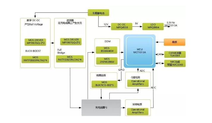
3. The simpler car charging solution is as below picture:
4. Program features:
Input voltage range from 9 V DC to 16 V DC (car battery supply range);
During the start-stop function, the input voltage can be reduced to 6 V DC level;
The receiver is rated for 15 W (at the output of the receiver) and is compatible with 5W receivers;
The design conforms to the Qi 1.2.4 specification, and the Qi software is used by the solution software;
System parameters, coil parameters and FOD parameters can be flexibly configured according to the specific needs of the end customer;
The NFC is reserved and the CAN function is integrated to lay the foundation for the intelligent development of the product.
5. Wireless charging technology point analysis
(1) the power supply of the control loop
The 12 V car battery input is connected to a buck converter (MPQ4558) with an output of 5 V to power the LDO (MPQ8904), MOSFET driver and CAN transceiver. The 3.3 V output of the LDO is primarily used to power the WCT1011A and other 3.3 V devices. Typically, DC-DC operates under light load conditions. The high efficiency at light loads is very important for this auxiliary buck converter.

(2). Power supply of the power circuit
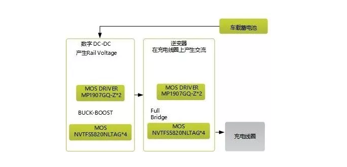
The Qi specification of the MP-A9 topology requires DC power control to control the power transmitted to the receiver. The power source is the vehicle‘s 12V battery, and the buck-boost obtains the regulated DC voltage (ranging from 1V DC to 24V DC) as needed. After that, the full-bridge inverter generates the AC loaded on the charging coil.
The Vrail voltage is generated by a digital Buck-Boost or analog Buck-Boost chip.
The digital Buck-Boost is directly controlled by the WCT1013A;
The analog Buck-Boost is controlled by a separate analog Buck-Boost chip, and the WCT1013A chip only controls the output voltage feedback.
The full-bridge inverter consists of two MOSFET drivers and four power MOSFETs. The MOSFET driver is powered by a stable 5V supply, reducing the power loss of the driver and MOSFET. The full-bridge inverter converts the Vrail voltage of the DC into an AC square wave with a frequency of 125 kHz and a duty cycle of 50%. The frequency range (120 kHz to 130 kHz) is defined in the Qi specification of the MP-A9 topology.
This article uses the digital Buck-Boost approach, the advantages are:
Cost-effective, hardware circuit is relatively simple, and easier to control, reducing the need for software development;
The control loop of the DC-DC converter is implemented by the main control firmware to achieve different parameter optimization.
Other technical points mainly include communication and foreign object detection (FOD) of the charging transmitter and the handset receiver.